homebuilt reflow solderingReflow-Löten im Eigenbau
Short notes - setup for homebuilt PCB prototypes
Since many PCBs I use contain quite a number of SMD parts, soldering by hand became increasingly tedious. So, I took the opportunity to build a poor man's reflow oven using the approach from github.com/apollo-ng/picoReflow, something I always wanted to try.
Below you see the results. It works nicely with a used oven and a bit of tinkering. Now I can reflow solder smaller components and those that cannot be soldered by hand. I already have a few ideas what I can use that for in the future.
Reflow oven
- Bought a used oven and repurposed it for reflow.
- Solid state relay (SSR) + Raspberry Pi Zero for control. Temperature is measured with a PT100.
- Based on this example: github.com/apollo-ng/picoReflow.
Reflow soldering
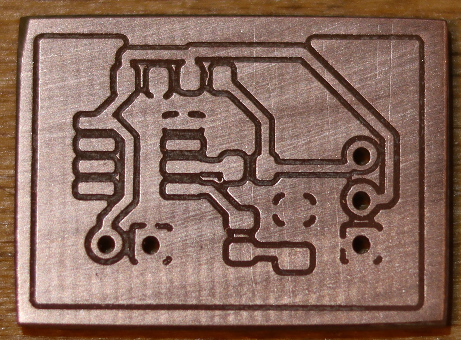
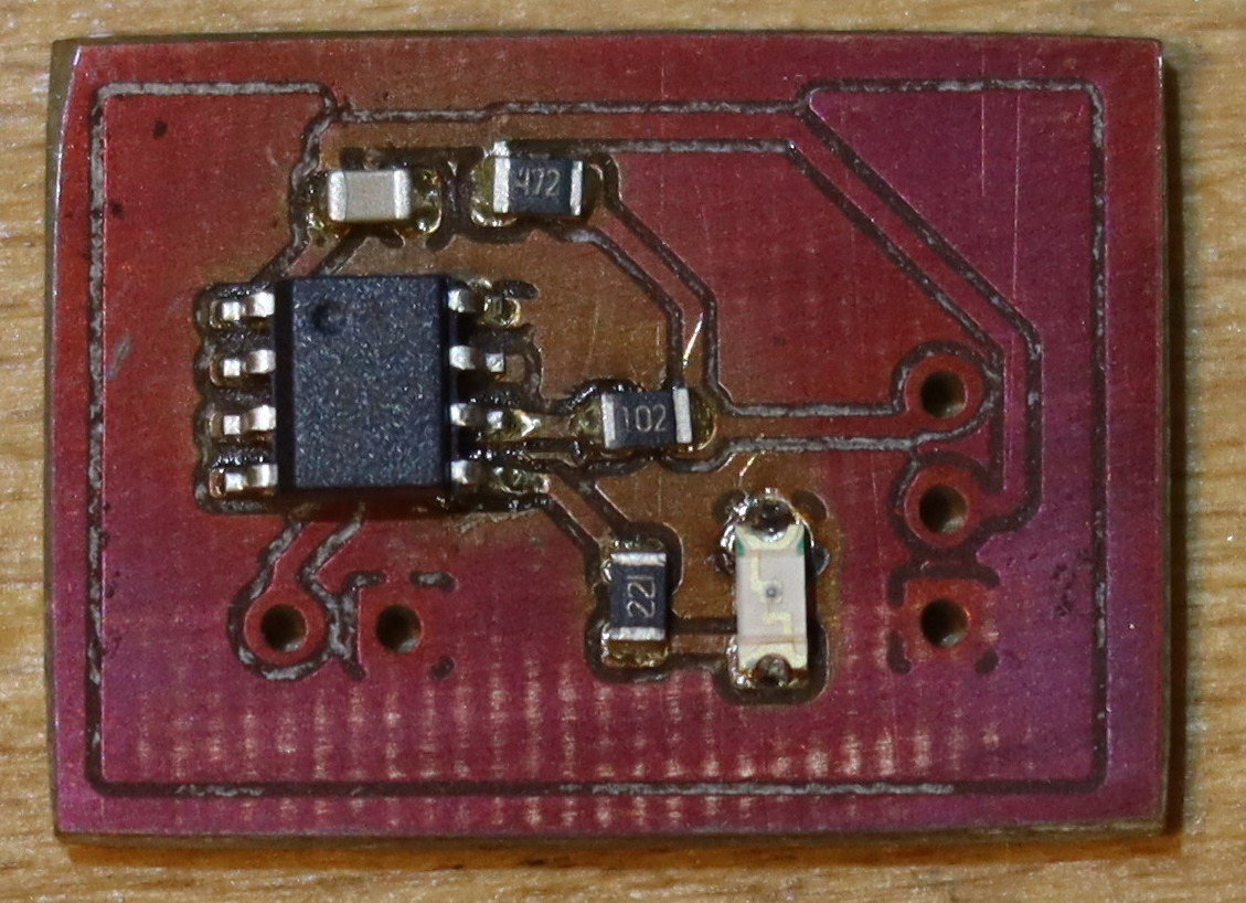
My first attempt with a self-milled, very simple PCB (how to build that: milling PCBs at home). Just an AVR tiny uC with a LED, breakout and programming interface.
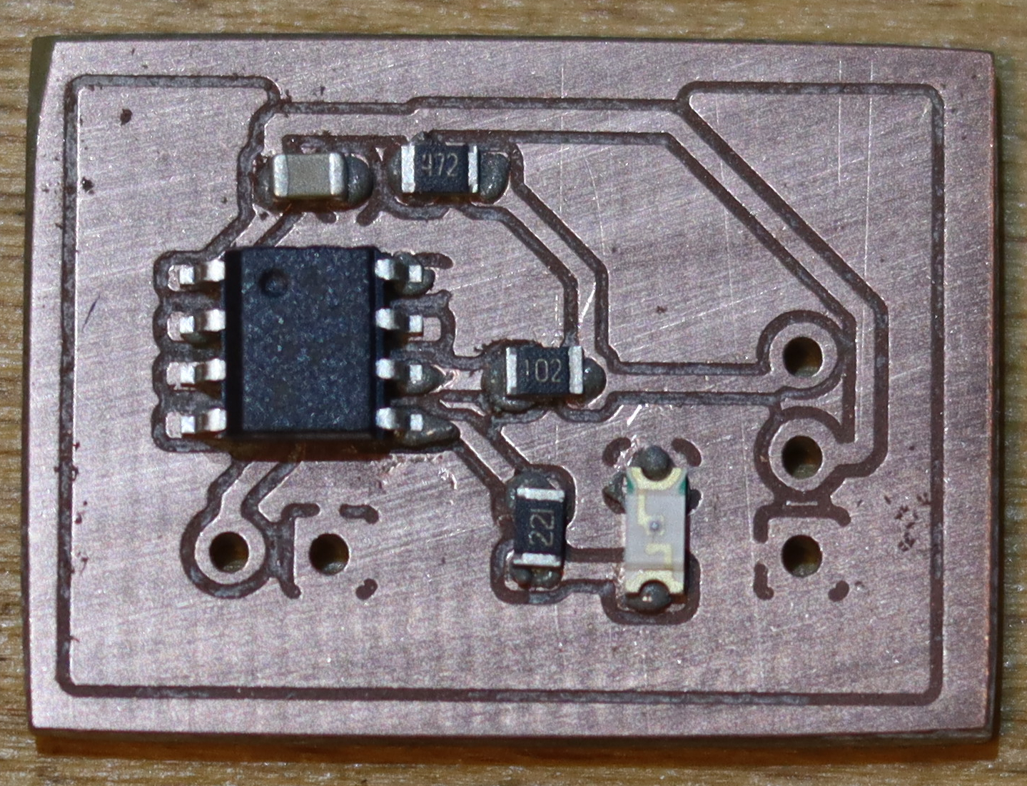
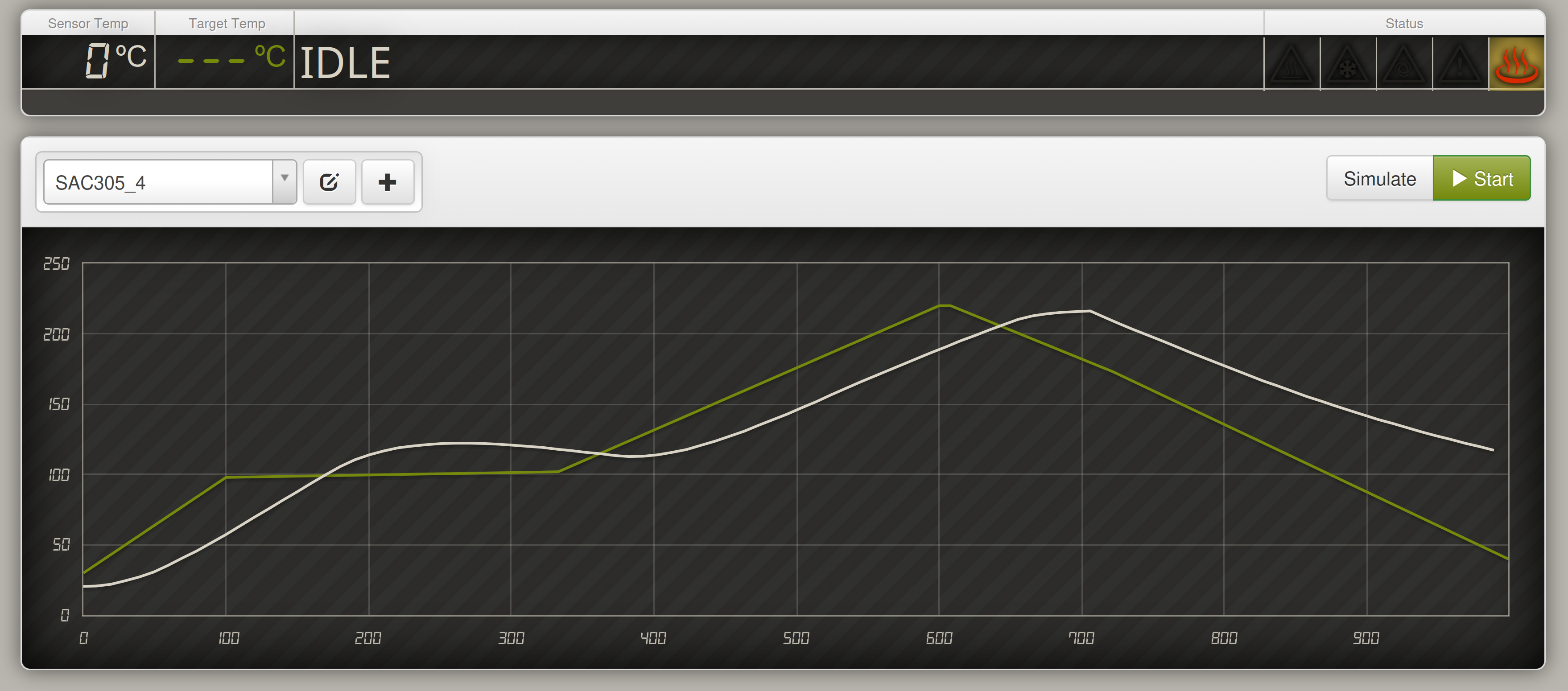
Next the PCB is put into the oven and the temperature ramp is executed.
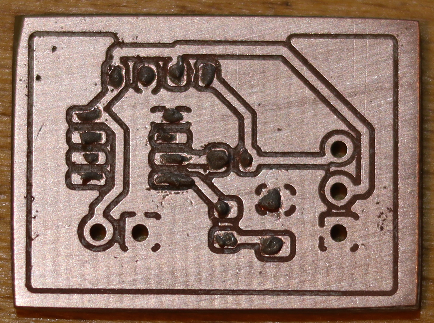
Applying soldering paste via home-made stencil
Using overhead transparencies I use the same mill as for the PCBs to manufacture a home-made stencil. Details coming soon.
Reflow soldering commercial PCB
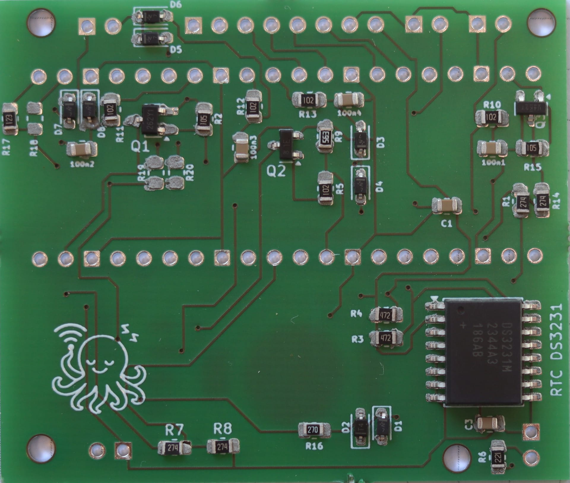
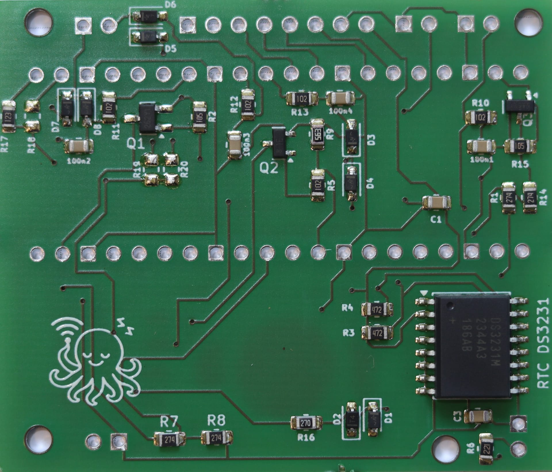
After I established the temperature profiles and did a few runs as shown above, I reflow-soldered a PCB for the inki project. In this case I use a commercial PCB and a stainless steel stencil. Applying the paste works very nicely as you would expect, see photo below with the components placed.
Kurze Notizen - Setup für Prototypen
Da viele meiner PCBs eine ganze Menge SMD-Teile haben, wurde Löten von Hand zunehmend lästig. Also habe ich die Gelegenheit genutzt und einen "poor man's" Reflow-Ofen nach dem Ansatz von github.com/apollo-ng/picoReflow gebaut - etwas, das ich schon lange ausprobieren wollte.
Unten sieht man die Ergebnisse. Es funktioniert gut mit einem gebrauchten Ofen und etwas Bastelei. Jetzt kann ich auch kleinere Bauteile und solche, die sich von Hand kaum löten lassen, per Reflow verarbeiten. Ich habe schon ein paar Ideen, wofür ich das in Zukunft nutzen kann.
Reflow-Ofen
- Gebrauchten Ofen gekauft und für Reflow umgebaut.
- Solid State Relay (SSR) + Raspberry Pi Zero zur Steuerung. Temperaturmessung mit PT100.
- Basierend auf diesem Beispiel: github.com/apollo-ng/picoReflow.
Reflow-Löten
Mein erster Versuch mit einer selbst gefrästen, sehr einfachen PCB (wie das geht: PCBs zu Hause fräsen). Nur ein AVR tiny uC mit LED, Breakout und Programmierinterface.
Danach kommt die PCB in den Ofen und der Temperaturverlauf wird gefahren.
Lötpaste per selbstgebauter Schablone
Mit Overhead-Folie nutze ich dieselbe Fräse wie für die PCBs, um eine eigene Schablone herzustellen. Details folgen.
Reflow-Löten einer kommerziellen PCB
Nachdem die Temperaturprofile passen und ich ein paar Läufe wie oben gemacht habe, habe ich eine PCB für das inki-Projekt reflow-gelötet. Hier nutze ich eine kommerzielle PCB und eine Edelstahl-Schablone. Das Auftragen der Paste klappt sehr gut, wie erwartet - siehe Foto unten mit den bestückten Bauteilen.